To start with there are two terms that I need to define in order for you to understand the introduction these are UV layout and UV mapping.
UV layout is the layout of a 3D models UV's. (UV's are like the vertex's of the texturing world).
UV mapping is the process you do in order to help arrange and sort out the UV layout.
Now that those two are defined I can move onto answering the question of what is UV mapping and why do we need to it? Basically UV mapping is the stage in between modelling and texturing, it is an important aspect of creating textures for 3D models. Creating a good UV layout allows us to tell maya how to apply the 2D texture images that we create. It is a bridge between 2D and 3D if you like. Having a good UV layout will speed up texture creation and will improve your results. In this tutorial I am going to be looking at some of the basics of UV mapping and show you some of the basic tools that allow you to edit the UV layout in the UV Texture Editor. I will be covering the four main UV Mapping techniques these are called Planar Mapping, Cylindrical Mapping, Spherical Mapping and Automatic Mapping. I will also briefly be looking at different projection types which simply means arranging the projection of the applied UV mapping technique and making sure it corresponds with the 3D model. I will show you how to take a UV Snapshot which is basically saving out an image of your UV layout so that you can use it for the texturing process. Hopefully after reading this tutorial you will have a basic understanding of the UV mapping process in maya and you'll be ready to move onto more complex projects.
Planar Mapping
In this part of the tutorial I am going to explain what planar mapping is and what is does. Firstly you'll need to open up maya and create a cube. You do this by making sure your in the Polygons sub menu which is indicated by a red rectangle in the screen grab below. You then go to Create which is located at the top > Polygon Primitives > Cube. Below is a screen grab which shows you how to create a cube and what the cube should look like once created.

You then need to apply a basic texture such as a checker board texture or a texture with colours and/or numbers. You do this in order to ensure your texture is nice and even all over the object. This is the next step and is very easy to do. We are going to use the checker board texture as it is really easy to create due to the fact maya already has the texture. So you simply hold down the right mouse click whilst holding the mouse over the cube. This will then give you a drop down list or box, you simply go down the list to Assign New Material which then gives you a second list, which you then go onto and click Lambert. The screen grab below shows you this.

The attribute editor at the right hand side will then change and should look like the one in the screen grab below. This is where you edit the Lambert material that you assigned to the cube so that you can apply the checker board texture.

It is always wise to give it a name, it can be any thing you want for this instance I've called it UV_Mapping_Texture.

You then click the little checkered box which is located on the right hand side of the box that says 'colour'. I have indicated what you need to click with a red box on the screen grab below.

A box will then appear that looks like the one in the screen grab below. This box allows you to select the texture that you want. You simply click Checker, I have indicated this with a red rectangle on the screen grab below.

This then applies the texture to the cube. Your cube should look like the one in the screen grab below.

You are now ready to start UV Mapping. The cube already comes with a good UV layout so it doesn’t really need UV mapping but for the point of this tutorial I am going to use a cube just to show you how planar mapping effects the UV's and explain when to use planar mapping.
So the next step is to select a face of the cube. The reason we are doing this is because planar mapping is a technique that is used for creating a UV layout of a flat plane like surface, such as a flat face of a 3D model. An example of when you would use the technique of planar mapping is when you want to texture one face differently to rest of the 3D model. Planar mapping solves this problem because it will create a separate shell for that face in your UV layout, therefore making it easier to texture as it is separate from the rest of the model in the UV layout.
To select a face of an object you simply hold down the right mouse click whilst the mouse is over the object, a drop down list will then appear. You then go down to the option that says Face and let go of the right mouse click. In doing so you have selected face mode. The screen grab below shows the drop down list and the option you should click (Face) this is highlighted in blue.

As I said before you are now in face mode. You can tell you are in face mode because when you hover your mouse over a face of the object, that face goes red. The screen grab below shows this.

You can now select a Face of the object. We are going to select the front face. To select a face you simply take your mouse and left click on the face that you want to select. You know when you have selected a face because the face goes a golden yellow colour, this is shown in the print screen below.

Now we have selected what face we want to UV map it is time to apply Planar Mapping. This is very straight forward firstly make sure you are still in the Polygons sub menu, for this tutorial you will not need to change this sub menu so just leave it set as the Polygons option. Now you simply click Create UV's, a drop down list will then appear, you then click Planar Mapping. The two screen grabs below show you exactly where to click.


However before you click Planar Mapping it is always wise to check the Planar Mapping options box before clicking. You need to check the options in order to make sure the UV's are going to be projected in the correct way. For example the face of the cube we have selected is on the Z axis, so we need to project our UV's on the Z axis so that the checker board texture we have matches the way that the face of the cube is facing. The screen grab below shows you how to access the Planar mapping Options box, it is highlighted in blue. You simply click this to open it.

Once clicking the Planar Mapping Options Box the box in the screen grab below will appear.

As you can see from the image above the Project Form is currently set to the X axis. This is a problem because the face of the cube that we have selected is on the Z axis. So we need to change this. This is easy to do you simply just select the circle next to Z axis. Your option box should now look like the one in the screen grab below.

You then simply click Project. You have now applied Planar mapping and will have a projection manipulator tool which allows you to edit the scale and position of the UV's against the texture. You can also edit this in the UV Texture Editor but I'll talk more about that later. Your cube should now look like the one in the image below.

The green blocks on the projection manipulator tool allow you to stretch the height of the UV's against the texture and the red blocks allow you to stretch the width of UV's against the texture. The blue blocks stretch the UV's against the texture while keeping the height and width in scale.
The screen grab below shows how the checker board texture gets manipulated when you stretch out the width using the projection manipulation tool.

You can also edit how the Projection Manipulator Tool works against the face that you have Planar Mapped. You don't need to do this for this cube as the Projection Manipulator tool works perfectly with the face of the cube that we have Planar Mapped, this is because we changed our Planar Mapping options to correspond with the face that we Planar Mapped. However it is not always as straight forward as that, sometimes the face you are trying to Planar Map is rotated against the axis so you have to edit the position or rotation of the Projection Manipulator tool in order to match the face.
You edit the Projection Manipulator Tool by click the little red cross symbol which in this instance is located in the bottom left hand corner of the Projection Manipulator Tool. I have indicated it on the screen grab below with a bold red square.

When you click this the Projection Manipulator Tool should change slightly, it should now look exactly like the one in the screen grab below. You now have the option of moving the whole position of the tool, and can do so via the axis arrows within the center of the tool.

You can then edit the rotation of the tool against the object. You do this by clicking on the light blue circle that is located in the center of the tool and surrounds the axis arrows. I have indicated where this light blue circle is with a bold red square in the screen grab below.

Once you have clicked the light blue circle your Projection Manipulator Tool will then change again, it will look exactly as it does in the print screen below.

You can now edit the position of the Projection Manipulator Tool and the rotation of it. You should use this technique to match the face of the object that you have UV Mapped, which will then allow you to match the texture better with the other corresponding faces. You can then easily swap the Projection Manipulator Tool back to editing the UV's of the planar map by clicking the little red cross in the bottom left corner of the Projection Manipulation Tool. I have indicated this with a bold red square on the screen grab below.

If your Projection Manipulator Tool has disappeared or is not showing up then you can manually select it. You do this by selecting the face that you have UV Mapped, you then select the projection manipulator tool from the inputs in the channel box on the right hand side. It will be titled something along the lines of polyPlanarProj1 but the title will vary differently depending on the UV mapping technique used, and the number of the tool will change depending on the order of when you UV mapped that face. In this instance the tool is called polyPlanarProj1, you simply click that title from the inputs in the channel box on the right and the projection manipulator tool will appear. The print screens below show you exactly where this is located and what to click, I have indicated this with bold red boxes.


Another reason why your Projection Manipulator Tool may not be showing up is because you have your history disabled, this is an easy mistake as the button that turns history on and off is located directly underneath the Create UV's button at the top. So it can quite easily be accidentally clicked without realizing. If your history is turned off then your Projection Manipulation Tool will not show up because your maya has no recollection of you UV mapping your model. So although the UV mapping will have actually been applied the projection manipulation tool does not appear. To fix this you simply click the button again and this will turn your history back on. The screen grab below shows where the history on/off button is located, I have indicated it with a bold red box.

If the button looks like it does in the screen grab below then this means your history is turned off and your projection manipulator tool will not appear.

You simply click this button again to turn the history back on. After clicking the button again the image of the button should change and look like the image in the screen grab below. This means your history is turned on and your projection manipulator tool will show up again. The projection manipulator tool will now appear again when UV mapping and you will be able to select it from the inputs menu in the attributes editor.

I have now covered the basics of Planar mapping so why not try and use Planar Mapping to UV Map each face of the cube, whilst doing this use the projection manipulator tool to match up the checkerboard texture with each face, thus creating a perfect UV Layout.
Now that I have covered the basics of Planar Mapping, its time to move onto the basics of Cylindrical Mapping.
Cylindrical Mapping
Cylindrical Mapping is very similar to Planar Mapping, it differs because it is a technique used for a different shape. Cylindrical Mapping is a technique used for UV Mapping cylindrical objects, examples of such objects would be handles, cans, bottles etc. For this part of the tutorial we are just going to be using a basic polygon cylinder. So first of all open up a new scene in Maya. Now we are going to create a cylinder. To do this click on Create > Polygon Primitives > Cylinder. The two screen grabs below show you exactly how to do this.


This will then have created a cylinder which looks similar to the one that I have created in the screen grab below. The only difference may be is that the cylinder that I have created is bigger this is because I scaled my cylinder bigger. I did this just so I could see what I am doing more clearly. You may like to do the same, you do this by clicking on the cylinder then pressing the letter 'R' on the keyboard. You then use the scale tool that appears to make your object bigger.

I then assigned the checkerboard texture to the cylinder. I did this by doing the exact same process that I did when assigning the checkerboard texture to the cube in the beginning of this tutorial. If your unsure how to do this then feel free to look back at how I did it for the cube. Below is an image of what your cylinder will now ruffly look like.

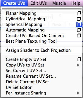
It is now time to use Cylindrical Mapping to rearrange the current UV's in order to project the texture perfectly around the cylinder as we want it. It is a very similar process to Planar mapping. Basically you select the cylinder by clicking on it, you then go to Create UV's > Cylindrical Mapping. The two screen grabs below show exactly where and what to click.


Like with Planar Mapping you can check the options before clicking on Cylindrical Mapping. You do this by clicking on the little box to the right hand side of cylindrical mapping. This is shown in the screen grab below and is highlighted blue.

Once you have clicked the box next to cylindrical mapping the cylindrical mapping option box will appear, it should look exactly the same as the one in the screen grab below. As you will see there are not many options for cylindrical mapping this is because you are UV mapping a 3D object rather than a flat face or plane so you do not need to choose what axis to project on. This is due to the fact that all of the axis will need to be projected on for cylindrical mapping. Therefore you do not really need to check the options when cylindrical mapping you can simply just click cylindrical mapping straight away.

Once you have applied cylindrical mapping to your cylinder the projection manipulator tool will appear.
In case you want to reselect this tool it is called polyCylProj1 and is located in the inputs of the Channel Box at the right hand side of the screen. Your cylinder should now look like the one in the screen grab below.
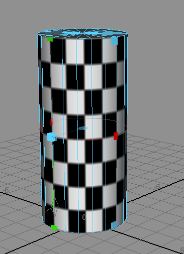
As you can see the projection manipulator tool is now present, it works in exactly the same way as the projection manipulator tool for Planar Mapping the only difference is that the tool is shaped to fit cylindrical objects.
As you may have noticed the cylindrical mapping caused the texture to just fit perfectly around the body of the cylinder, but the top and bottom faces now no longer have the texture on them. You can now use what you know about Planar mapping to UV map the top and bottom faces.
Remember when Planar Mapping to check the Planar Mapping options before you apply the Planar Map. When Planar mapping the top faces of the cylinder you should change the project form to the Y axis. The screen grab below shows this.

I then applied the Planar Map to the top of the cylinder by clicking Project in the Planar Mapping Options Box, the screen grab below shows how the top the cylinder then looked.

After applying the Planar Map to the top faces of the cylinder I scaled the UV's using the projection manipulator tool. I tried as best as I could to line up and match the checkerboard texture of the body of the cylinder to the checkerboard texture of the top of the cylinder. The screen grab below shows how I scaled the projection manipulator tool to match the texture from the different parts of the cylinder.

After matching up the checkerboard texture as best as I could I finally had the top of the cylinder matching the body of the cylinder. The screen grab below shows my final result.

See if you can take what you have learnt and Planar Map the bottom faces of the cylinder, using the projection manipulator tool to scale and position the checkerboard texture to match the checkerboard texture that is on the body of the cylinder.
So now I have covered the basics of Cylindrical Mapping its time to cover the basics of Spherical Mapping.
Spherical Mapping
Spherical Mapping has the same principles as Planar mapping and Cylindrical Mapping the only difference is that spherical mapping is used for spherical objects. Examples of spherical objects that you may have to UV map would be something like a door handle, an football, basket ball or tennis ball, an eye ball etc. For this part of the tutorial we are going to create a sphere. You do this in exactly the same way that we did for creating the cube and the cylinder. You go to Create > Polygon Primitives > Sphere. The two screen grabs below show you how to do this.


Once you have done this a sphere will have now been created and should look similar to the one in the screen grab below.

Now we need to assign the checkerboard texture to the sphere. Follow the exact process that we did when we applied the checkerboard texture to the cube and the cylinder. Your sphere should now look like the one in the screen grab below.

Now it is time to apply Spherical mapping. You will find this in the same place where we found Planar mapping and Cylindrical mapping. You simply click on the sphere so that it goes green, you then click Create UV's > Spherical Mapping. Before you do so you may want to check the Spherical Mapping Options, if so the same process applies from before you simply click the little Option Box next to Spherical mapping.
For the same reasons as Cylindrical mapping there are not many options in the Spherical Mapping Options Box so you don't really need to check them you can simply just click Spherical Mapping. The two screen grabs below show you where to find Spherical Mapping.


The two screen grabs below show you how to open up the Spherical Mapping Option Box and what the Spherical Mapping Option Box looks like once opened. However you do not really need to check the options of Spherical Mapping as we do not need to change anything.

Once you have applied Spherical Mapping to the sphere you will notice the checkerboard texture will have now altered slightly and the projection manipulator tool will have now appeared. It should look similar to the screen grab below.

The projection manipulator tool for spherical mapping works in the exact same way as it does for planar mapping and cylindrical mapping. I suggest you now experiment using the projection manipulator tool for spherical mapping, as this will give you a better understanding of how you can change the spherical UV's that you have just created to manipulate the checkerboard texture. Remember you can rotate and reposition the projection manipulator tool against the object as well as use it to scale the UV's.
You can use all three UV mapping techniques on as many parts of one 3D model as you like. For instance say you have a model which contains a plane, a cylinder and a sphere, you can simply select the face/faces (if it is all one mesh that is) that you want to UV map such as the cylindrical part of the model and use the required UV mapping technique e.g cylindrical mapping. Or if it is a model that has not been combined and you can select each part then you simply click the part of the model that you want to UV map, for example the spherical part and use the required UV mapping technique e.g. spherical mapping. You then use the projection manipulator tool to match and line up the checkerboard texture with the rest of the parts of the model. Like what we did with the cylinder where we used cylindrical mapping for the body and then used planar mapping for the top and bottom, making sure we lined up the checkerboard texture to match each part of the cylinder as we went along.
So now you have learnt the basics of Spherical Mapping and how you can use it, it is time to cover the basics of Automatic Mapping.
Automatic Mapping
Automatic mapping is a UV mapping technique that is used for more complex 3D models. It is a quicker option than having to select each part of the model and UV mapping it indivually. An example of when you would use Automatic Mapping would be a 3D model of a human head. If you have a 3D model that is more complex than a flat/ plane object, cylindrical objects or spherical objects then automatic mapping is a good UV mapping technique to use. However after using automatic mapping you will often have to do a lot of editing to the UV layout in the UV Texture Editor. So after I have shown you the basics of automatic mapping then I will show you the basic's of the UV Texture Editor and show you some basic tools that allow you to edit the UV Layout.
The way Automatic Mapping works is it uses a series of planes to automatically project the UV's onto the model that you are using, therefor creating a UV layout for the whole model.
In order to show you how to apply automatic mapping and show you how it works I am going to be using a more complex 3D monster model that was built for my other animation project. Unfortunately you wont have this model to follow along with so you could just use a cube or find a free complex model to use from the internet.
Below is an image of the model of the monster that I am using to demonstrate Automatic Mapping.

As you can see planar mapping, cylindrical mapping and spherical mapping are not really sufficient enough for the process of UV mapping this model, and if I were to use them it would take me a very long time to UV map the whole monster.
I then assigned a checkered texture to the monster model. I used the same process that I used to assign the checkered texture to the cube, cylinder and sphere. The screen grab below shows how the monster model looked after I had applied the checkered texture.

The next stage is to apply Automatic Mapping. Automatic Mapping is located in the same place as planar mapping, cylindrical mapping and spherical mapping. You simply click on the model so that it goes green, you then click on Create UV's at the top of the maya window, a drop down list will appear and you then click Automatic Mapping. This will now have applied Automatic Mapping to the model. The two screen grabs below show you exactly how to do this.


However before clicking Automatic Mapping you defiantly need to check the Automatic Mapping Options. You need to do this because the automatic mapping options effect the UV layout of the automatic map that you are about to create. You open the Automatic Mapping Options Box by clicking on the little box that is located to the right of Automatic Mapping. The screen grab below shows you exactly where it is, in the screen grab below it is highlighted in blue.

When you click the box next to Automatic Mapping the Automatic Mapping Options Box will then open. It will look like the one in the screen grab below.

If you then click Project which is located in the bottom left corner. The Box will close and you will have applied automatic mapping to the model. The screen grab below shows my monster model with automatic mapping applied.

As you can see there are now 3 planes around the model these planes are projecting the automatic mapping onto the model. You can use the tool in the middle to position and rotate the planes.
However having 3 planes is not really ideal for this model as it means we only have 3 faces being projected. We have the top, the front and the right side being projected when ideally we want all the faces of the model to be projected. This is easily resolved, you simply open up the Automatic Mapping Options Box again and you will see there is an option in it called Planes:, it has a drop down list next to it. I have indicated it with a bold red box on the screen grab below. At the moment it is currently set to 3 therefore when we apply automatic mapping we only have 3 planes projecting onto the model.

I personally use 6 planes most of the time when using automatic mapping, and in this instance of using automatic mapping to UV map the monster I definitely need 6 planes.
If I have 6 planes then I will be projecting the top, front, right side, left side, bottom side and back side of the model. Therefore I am getting a projection of all of the faces of the model which means I get a UV layout for the whole model.
Changing planes from 3 to 6 is very easy, you simply click on the drop down list next to planes in the automatic mapping options box. The drop down list will appear and you will have the option of choosing from several numbers. You will see 6 is an option in the drop down list. You simply just click on 6, then click project at the bottom of the automatic mapping options box. The screen grabs below show you exactly what to do and where to click is indicated with bold red boxes.


Once clicking project you will now see that 6 planes are now surrounding the model. This is good because we now have all faces of the model being projected, therefore we get a UV layout for the whole model. The screen grab below shows my monster model with the 6 planes surrounding it.

Another thing you can do in the Automatic Mapping Options Box is change the UV Shell Layout. This will make the next stage of editing the UV layout a lot easier. At the moment the Shell Layout in the Automatic Mapping Options Box is probably set to Overlap. This means the shells of the UV Layout will be overlapping each other in the UV Texture Editor. The screen grab below shows the overlapping UV Layout.

As you can see from the screen grab above all the different shells are overlapping each other. This makes it very unclear as to see what parts of the model you are looking at.
So you can change the setting which will spread the shells out in different ways which will then make it a lot easier to start to recognise what shell represents what part of the model. You can do this by changing the Shell Layout option to Into Square this will arrange the shells within the square of the UV texture editor. Or you have the option of arranging the shells so they are spread out and set up along the U axis of the UV texture editor, you do this by selecting Along U.
In order to do this you need to open the automatic mapping options box again. You then click on the drop down list next to Shell Layout:. This is indicated on the screen grab below with a bold red box.

You simply click on the drop down list and a list of options will appear. You go to the option you want and click on it. This will then select the option. The two screen grabs below show you how to select the Into Square and Along U options, I have indicated this with bold red rectangles.


After selecting the option from the drop down list you then click Project which is located at the bottom left of the Automatic Mapping Option Box. This is shown in the screen grab below and is indicated with a bold red box.

As you can see from the screen grab above I selected the Shell Layout option as Into square, I recommend using this option because this is the option where the UV layout is most spread out and everything can be seen a lot clearer. The screen grab below shows how the UV layout now looks once I have applied automatic mapping with the Shell Layout set as Into square.

As you can see from the screen grab above the UV layout is now a lot more clearer compared to UV Layout before.
Now I have shown you the basics of Automatic Mapping it's time to move onto the basics of editing UV layouts in the UV Texture Editor.
Editing UV Layouts In The UV Texture Editor
Once you have UV mapped your model its then time to check the models UV layout. You do this in the UV Texture Editor. You need to make sure your model has a good UV layout so that the 2D texture you apply wraps perfectly around the 3D model. You also need to make sure your models UV layout is good so that you can recognise what part of the UV layout represents what part of the model. I am going to use the UV layout that I got from automatic mapping the monster model that I was using previously. I am going to show you a few basic tools in the UV Texture Editor that allow you to edit the UV layout.
To open up the UV Texture Editor you first click on the model or object that you have UV mapped so that it goes green. You then click Window which is at the top of the maya window, the list will then appear and you click on UV Texture Editor. The two screen grabs below show you exactly where and what to click.


Once you have clicked on UV Texture Editor, the UV Texture Editor will then open in a separate window. It should look like it does in the print screen below.

As you can see you have your tools and options along the top of the UV Texture Editor and you have your UV grid with the UV layout underneath. Each individual part of the model in the UV Texture Editor is called a shell. As you can see all of the shells are located in the top right quarter of the UV grid which is often known as the 0 to 1 space, this is where you place your texture/ textures, so that is where all of the shells should be placed. Think of this top right quarter as your texture file.
Below is a screen grab which gives you a closer view of the shells in the 0 to 1 space. As you can see there are lots of little tiny shells at the top and the 0 to 1 space is very crowded. It is slightly apparent as to what part of the model each shell represents however there are holes missing from some of the shells and the UV layout is just generally a bit of a mess. So what I need to do is to find homes for the tiny shells and fill in the holes. What I mean by finding homes for the tiny shells is all of these shells represent parts of the model therefore they can all be attached to parts of each other.
The way you do this is by simply selecting an edge. You select an edge, the edge will then turn orange and its corresponding edge that it can be joined to will also turn orange. You then start to piece the UV layout together like a jigsaw by sewing the edges together. You should not sew all of the pieces together to make one big shell as this will make the texturing process too difficult. You should sew the shells together to make a UV layout that makes sense. So I should have a shell for the front of the body, the back of the body, the whole head, each arm and leg with the feet and hands. Remembering to keep in mind where you want the seems of the texture to be located. Seems are where the texture joins together. They are inevitable, you will always get them. The trick is to loacte them so that they are hidden or are where a seem would naturally be located. Such as places like along the back of the head so it is hidden under the hair or along the edge of an open mouth.

Firstly you can move shells, scale them and rotate them you can do this by clicking on the little button that I have indicated on the screen grab below with a bold red box.

The print screen below is a picture of the button up close.

Once you have clicked this button it will then have the blue square around it, this means when you click on any UV point it will select that whole shell. Once a shell is selected you can then use the keyboard shortcuts which will make the appropriate tool appear that will allow you to move, scale and rotate that selected shell. The keyboard short cut for the tool that will allow you to move the shell is W. The keyboard short cut for the tool that will allow you to scale the shell is R, and the keyboard shortcut for the tool that will allow you to rotate the shell is E.
The screen grab below shows you how I have selected a shell and rotated it, rescaled it and repositioned it.

You can also do this for each individual UV points which will allow you to edit the structure of the shell. You simply click and hold down the right mouse button while the mouse is over a shell. You then go to UV and let go of the right mouse click you can now select individual UV's. You can move them, scale them and rotate them by using the same keyboard short cuts from above. The screen grab below shows you the menu that comes up when holding down the right mouse click over a shell. I have indicated what to click on with a bold red rectangle.

To select an edge you simply do the same process by clicking and holding down the right mouse click whilst the mouse is over a shell. Instead of clicking UV you click Edge. The screen grab below shows you what to click on, it is highlighted in blue.

After you have clicked edge you can now select an edge of a shell. Once you have selected an edge it will turn orange and so will the edge/ edges that correspond with that edge. To show you what I mean I have selected all of the edges of one shell. All of the edges that can be sewn to the edges of that shell are highlighted orange. On the screen grab below I have indicated the shell with all the edges selected with a bold red arrow pointing towards it.

As you can see from the screen grab above there are edges that are not apart of the shell that are selected. This means these edges are candidates that can be paired with the edges of the shell that is selected. As you can see if we sewed some of these edges together it would get rid of a lot of the tiny shells. This is exactly what we want to do. You have to pick the best edges to sew together to make a shell that makes the most sense.
To sew an edge together you simply click the edge and then you either click one of two buttons. There is the Sew button which simply stretches the edges so that they meet half way and get sewn together. You would use this button if you are moving a shell into place then you want to sew it to its corresponding edge. Or the second button which is the Move and Sew button, this is the button that you will probably use the most. It basically moves the edge and its shell to the corresponding edge and sews them together. That way you don't have to move all of the shells manually.
So I selected two edges from a hole missing from the shell of the front of the body. The screen grab below shows this and the edges are highlighted in orange.

There were two corresponding edges amongst all of the tiny little shells at the top of the UV layout. The screen grab below shows the two edges that can be paired with the two edges from the screen grab above. Again the edges are highlighted orange.

I am going to use the Move and Sew button to move this tiny shell into place and sew the edges together. The screen grab below shows where the Sew button and the Move and Sew button are located they are indicated with bold red boxes around them.

The Sew Button looks like this:

and the Move and Sew Button looks like this:

So I selected the two edges and clicked on the Move and Sew button. The screen grab below shows the results as you will see the tiny two piece shell has now moved into the hole that it was missing from in the shell of the front of the body and the edges have been sewn together. Therefore making the tiny shell apart of the big shell. I have indicated the change by putting a bold red circle around it on the screen grab.

As you can see from the screen grab above there is now a corner overlapping. We want the shell to be as neat as possible because the neater the shell the better the texture. So I am going to use the technique that I used earlier and select the individual UV and move it so that it is not overlapping. You do this by clicking and holding down the right mouse click whilst the mouse is over the shell, you then move the mouse to UV and let go of the right mouse click. You can now select the separate UV's of the shell. The screen grab below shows you what you need to click, it is highlighted in blue.

I can now select the UV. When you have selected a UV point, the UV point shows up with a bright green dot. The screen grab below shows the selected UV point.

I then pressed the keyboard short cut W and the move tool appears. I then dragged the UV point into a better position. The two screen grabs below show the move tool and the new position of the UV point.


There are some other basic tools which are useful when editing UV layouts in the UV Texture Editor. I have drawn bold red boxes around them on the screen grab below.

I'm now going to explain what each of these buttons do.

The four buttons in the screen grab above basically just edit the whole UV layout, or the selected shell or shells. The two red circle symbols at the bottom of the image simply rotate the layout or selected shell/ shells in different directions. The top two buttons that are at the top of the image flip the UV layout, or the selected shell/ shells in the U direction or the V direction.

The button in the image above allow you to cut UV's. This button does the reverse of sewing edges. This can come in handy if you want to move a part of a shell and sew it to another shell. You simply select the edges that to want to separate and then click this button and it splits edges up again.

The button in the image above simply adds a grey background to the grid in the 0 to 1 area, this is so the UV layout becomes more visible. You can make the grey darker by clicking on the button in the image below again this is just to make the UV layout more visible.

The button in the image above only works when the button above it is on. This button simply just darkens the grey background of the grid in the 0 to 1 area. This is so you can see the UV layout more clearly.

The button in the image above turns the grid lines on and off. Again another button which just helps you to see the UV layout better.

The button in the image above makes the lines of the shells bolder this is so they stand out against the grid and the background colour behind them.

The button in the image above allows you to turn the image of the applied texture on and off as a background for the 0 to 1 area. This is so you can see what shell is covering what part of the texture.
Other techniques you can use for editing UV layouts can be found in the Polygons menu in the UV texture editor.
There are 3 techniques that I recommend. You can use an option called Relax which automatically moves and distributes UV's to space them out more, this is to give better texture distribution.
Then there is the option called Unfold which unfolds the selected UV's which spreads them out within their own shell.
Then there is Layout this comes in very handy when you have moved all of your shells all over the place. You simply select the shells and click layout and it automatically rearranges the shells neatly within the 0 to 1 area on the UV grid space. So say you had moved a shell out of the grid, you simply select that shell click layout and it will automatically arrange itself in the 0 to 1 area on the UV grid. The screen grab below shows you where you can find these 3 techniques, they are marked with a bold red box around them.

I continued to use all of these basic tools and techniques to finish the UV layout of the monster model that I was using. Below is a screen grab of the finished UV layout for the monster model.

So now you know the basic tools and techniques of editing UV layouts in the UV texture editor you can now start to create some good UV Layouts that will allow you to do a good job when texturing. That leaves me with only one thing left to show you and thats UV snapshots.
UV Snapshots
UV snapshots are basically a way of saving out your UV layout as an image. This then allows you to open up the UV layout in another piece of software such as photoshop, where you can then apply a texture or textures. Once you have applied the texture or textures you can then save the file and load it back into maya which will then project that texture onto your 3D model.
Taking a UV Snapshot is easy you simply select your whole UV layout in the UV Texture Editor, you then go to Polygons. A drop down list will appear you go down the list to the bottom and click UV Snapshot.... The screen grab below shows you exactly where and what to click.

Once you have clicked UV Snapshot... the UV Snapshot Option Box will appear in a separate window. This is where you can select the destination of where your UV snapshot is going to be saved. You can also choose from a drop down list what image format you want to save the UV snapshot as, such as a targa or tiff file. You can also choose from a drop down list what part of the UV Layout you want to save such as the 0 to 1 area or the entire range of the UV layout. The screen grab below shows the UV snapshot options box.

The screen grab below shows you where you pick where you want to save the UV snapshot. You do this by clicking on the Browse... button. This is indicated with a bold red box.

The screen grab below shows you where to select the image format that you want to save the UV Snapshot as.

The screen grab below shows you where you can select the UV range of the UV snapshot.

Once you have selected where you want to save the UV snapshot and selected the options that you want. You simply click OK which is indicated in the screen grab below with a bold red box.

Now that your UV snapshot has been saved you can use the UV snapshot and start texturing.
That brings me to the end of this basic UV Mapping Tutorial I hope you found it Beneficial.